In this post we will review how to script a sketch in FreeCAD using python. Our goal is to create a chain link model which we will do entirely via python scripting. This post covers how to script a sketch in FreeCAD and also how to create an additive pipe in FreeCAD using python. The code is part of a larger macro that generates chain link models based on parameters you enter into a dialog box. See the following related posts:
The FreeCAD chainlink generator macro – this post provides the full code and explains how the macro works. If you just want to run code and generate chain links ready to 3D print start here.
The FreeCAD chainlink generator UI – This post explains how the user interface code works.
Create a Part and Body
The first step in the process is to create a new Part and Body. The Body will eventually have the additive pipe that defines the first link in the chain link.
def createPart(self, name):
   # create the chainlink part
   print("create the chainlink part")
   Gui.activateWorkbench("PartDesignWorkbench")
   self.partChainLink = App.activeDocument().addObject('App::Part',name)
   self.partChainLink.Label = name
   self.partChainLink.Type = "ChainLink"
   Gui.activateView('Gui::View3DInventor', True)
   Gui.activeView().setActiveObject('part', self.partChainLink)

def createBody(self, name):
   # create the body for the first link
   print("create the body for the first link")
   self.bodyLink = App.activeDocument().addObject('PartDesign::Body','Body')
   self.bodyLink.Label = 'Link'
   # add the body to the chainlink part
App.activeDocument().getObject(self.bodyLink.Name).adjustRelativeLinks(self.partChainLink)
   App.activeDocument().getObject(self.partChainLink.Name).addObject(self.bodyLink)
   # make the body the active object
   Gui.ActiveDocument.ActiveView.setActiveObject('pdbody',self.bodyLink)
The code above is divided into two methods, one for the Part and one for the Body. Looking at the code in createPart() we see it activates the Part Design Workbench. Then it creates an “App::Part” object in the activeDocument. Then it sets the Label and Type properties of the part. Finally, we activate the “Gui::View3DInventor” view. This causes FreeCAD to display the 3D window to view the sketch.
The createBody() method creates the “PartDesign::Body” object and then sets the Label property. It then uses the “adjustRelativeLinks method of the newly created Body to link it to the Part. Finally the script uses the “addObject” method to add the Body to the Part.
Create the Path Sketch
This is a sketch of one link in the chain link. It is the “path” sketch needed for the additive pipe object.
def createPathSketch(self,name):
   # create a sketch for the link path
   print("create path sketch")
   self.pathSketch = self.bodyLink.newObject('Sketcher::SketchObject','Sketch')
   self.pathSketch.Label = name
   self.pathSketch.Support = self.bodyLink.Origin.OriginFeatures[3]
   self.pathSketch.MapMode = 'FlatFace'
   self.pathSketch.Visibility = False
The code above creates a sketch object called pathSketch using the newObject method of the body object created earlier. This is how the sketch is made part of the body object. Then we set the label of the sketch to the name parameter. The next line sets the “Support” property of the sketch to one of the planes of the body. If you look at the tree view in FreeCAD you will see the “Origin” under the body. Inside the Origin are the three axis and three planes of the body. OriginFeatures[3] picks the first plane. Finally, we set the “MapMode” and “Visibility” properties.
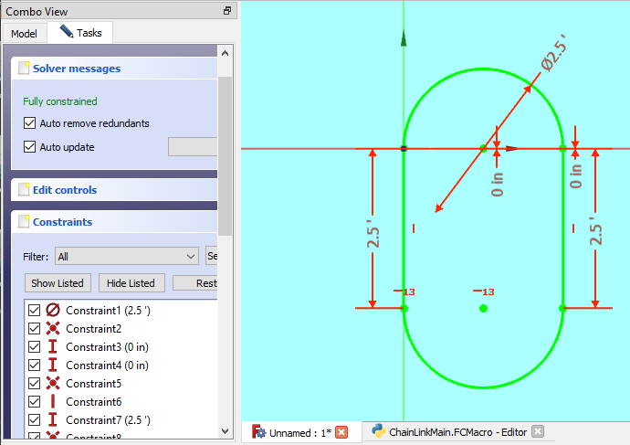
def drawPathSketch(self):
   # draw the sketch for the link path
   print("draw path sketch")
   linkEdgeLen = self.scale(self.linkLen) - self.scale(self.linkWidth)
   # top arc
   self.pathSketch.addGeometry(Part.ArcOfCircle(Part.Circle(App.Vector(25,0,0),App.Vector(0,0,1),50),0,3.14159265),False)
   self.pathSketch.addConstraint(Sketcher.Constraint('Diameter',0,App.Units.Quantity("{} {}".format(str(self.scale(self.linkWidth)), self.unit))))
   self.pathSketch.addConstraint(Sketcher.Constraint('Coincident',0,2,-1,1))
   self.pathSketch.addConstraint(Sketcher.Constraint('DistanceY',0,3,0))
   self.pathSketch.addConstraint(Sketcher.Constraint('DistanceY',0,1,0))
   # left line
   self.pathSketch.addGeometry(Part.LineSegment(App.Vector(0,0,0),App.Vector(0,linkEdgeLen * -1,0)),False)
   self.pathSketch.addConstraint(Sketcher.Constraint('Coincident',1,1,0,2))
   self.pathSketch.addConstraint(Sketcher.Constraint('Vertical',1))
   self.pathSketch.addConstraint(Sketcher.Constraint("DistanceY", 1,2,1,1, App.Units.Quantity("{} {}".format(str(linkEdgeLen), self.unit))))
# right line
   self.pathSketch.addGeometry(Part.LineSegment(App.Vector(0,0,0),App.Vector(0,linkEdgeLen * -1,0)),False)
   self.pathSketch.addConstraint(Sketcher.Constraint('Coincident',2,1,0,1))
   self.pathSketch.addConstraint(Sketcher.Constraint('Vertical',2))
   self.pathSketch.addConstraint(Sketcher.Constraint("DistanceY", 2,2,2,1, App.Units.Quantity("{} {}".format(str(linkEdgeLen),self.unit))))
   #bottom arc
   self.pathSketch.addGeometry(Part.ArcOfCircle(Part.Circle(App.Vector(self.scale(self.linkWidth)/2,linkEdgeLen*-1,0),App.Vector(0,0,1),self.scale(self.linkWidth)/2),-3.14159265, 0),False)
   self.pathSketch.addConstraint(Sketcher.Constraint('Coincident',1,2,3,1))
   self.pathSketch.addConstraint(Sketcher.Constraint('Coincident',2,2,3,2))
   self.pathSketch.addConstraint(Sketcher.Constraint('Horizontal',1,2,3,3))
Add An Arc To The Sketch
Now for the fun part – adding geometry to the sketch itself.
self.pathSketch.addGeometry(Part.ArcOfCircle(Part.Circle(App.Vector(25,0,0),App.Vector(0,0,1),50),0,3.14159265),False)First, we create the top arc using the “Part.ArcOfCircle” method. The Part module contains methods for all the geometry shapes that can be added to a sketch. You can see more examples here. To create an ArcOfCircle you need to supply a circle, along with the start and end angles in radians. The Part.Circle is defined using three points which are hardcoded. The points don’t really matter as we will adjust the resulting arc to what we want using constraints.
Add Diameter Constraint To The Arc
Now let’s add the constraints.
self.pathSketch.addConstraint(Sketcher.Constraint('Diameter',0,App.Units.Quantity("{} {}".format(str(self.scale(self.linkWidth)), self.unit))))The “addConstraint” method of the sketch is what you use to add constraints. First we add a “Diameter” type constraint which requires two additional parameters – the arc or circle that is being constrained and the amount of the constraint, i.e. the diameter. In the example above I referenced the arc using it’s index in the list of objects in the sketch so “0” refers to the top arc which is the first object we defined. We supply quantities using the “App.Units.Quantity()” method which takes in a string (for example “50 mm”).
App.Units.Quantity("{} {}".format(str(self.scale(self.linkWidth)), self.unit))To create the proper string value for “App.Units.Quantity” we use the Python format method of generating strings from variables. “self.scale(self.linkWidth)” takes the link width entered into the UI and scales it according to the scale factor entered into the UI. The unit can be either “mm” or “in” which is also defined in the UI.
Coincident Constraint
self.pathSketch.addConstraint(Sketcher.Constraint('Coincident',0,2,-1,1))Now we will add a Coincident constraint. The Coincident constraint takes 4 parameters:
1. the line that doesn’t move. We specified “0” which is the index into the objects defined in the sketch. “0” is the first item in the list which is the arc we defined above.
2. the point on the “non-moving” line (or arc in our case). We specified “2” which is the 2nd point on the arc. This is the left most point.
3. the line that will move. We specified “-1” which actually refers to the Horizontal “X” axis and not an actual line.
4. the point on the line that will move. We specified “1” which refers to the origin.
The net effect of this constraint is to anchor the left-hand side of the arc to the origin.
For a more detailed explanation of scripting constraints see here.
Vertical Distance Constraint
self.pathSketch.addConstraint(Sketcher.Constraint('DistanceY',0,3,0)) Next we add a “DistanceY” constraint to the arc. DistanceY takes 3 parameters as follows:
- The index to the object being constrained. We specified “0” which refers to the arc.
- The point on the arc. We specified “3” which is the center point of the arc.
- The distance to the origin. We specified “0”.
The net effect of this constraint is to lock the center point of the arc on the horizontal axis.
The next constraint is just like the previous one. It adds a DistanceY constraint to the right hand point of the arc. Now the arc is locked in place.
Add A Line Segment To The Sketch
Next we will add a Line segment.
self.pathSketch.addGeometry(Part.LineSegment(App.Vector(0,0,0),App.Vector(0,linkEdgeLen * -1,0)),False)The line segment is defined by it’s starting point and it’s ending point in 3 dimensional space. These are specified using the “App.Vector” method. The starting point is the origin (0,0,0). The ending point is down the Y axis an amount that was calculated earlier in the script and is the length of the link.
Now we add constraints to the line segment.
self.pathSketch.addConstraint(Sketcher.Constraint('Coincident',1,1,0,2))
   self.pathSketch.addConstraint(Sketcher.Constraint('Vertical',1))
   self.pathSketch.addConstraint(Sketcher.Constraint("DistanceY", 1,2,1,1, App.Units.Quantity("{} {}".format(str(linkEdgeLen), self.unit))))
The first constraint is a Coincident constraint that locks the beginning of the line to the end of the arc.
The second constraint is a Vertical constraint that sets the line to being vertical.
The third constraint is a DistanceY constraint that sets the distance between the two points on the line. Note the use of the App.Units.Quantity() function to provide the distance as described earlier.
The rest of the code adds a second line segment like the one described above but attached to the other side of the arc. Finally, the bottom arc is added and linked to the line segments. This completes the sketch of the link path.
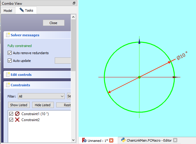
Create The Profile Sketch
def createProfileSketch(self,name):
   # create an empty sketch for the link profile
   print("create a sketch for the link profile")

   self.profileSketch = self.bodyLink.newObject('Sketcher::SketchObject','Sketch')
   self.profileSketch.Label = name
   self.profileSketch.Support = self.bodyLink.Origin.OriginFeatures[4]
   self.profileSketch.MapMode = 'FlatFace'
def drawProfileSketch(self):
# draw the sketch for the link profile
print("draw profile sketch")
self.profileSketch.addGeometry(Part.Circle(App.Vector(0.000000,-0.000000,0),App.Vector(0,0,1),10),False)
self.profileSketch.addConstraint(Sketcher.Constraint('Diameter',0,App.Units.Quantity("{} {}".format(str(self.scale(self.linkDiameter)), self.unit))))
self.profileSketch.addConstraint(Sketcher.Constraint('Coincident',0,3,-1,1)) The profile sketch defines the profile of the additive pipe. In our case, the profile is a simple circle. The code is shown above and is much like the code explained in the path sketch.
Script Additive Pipe
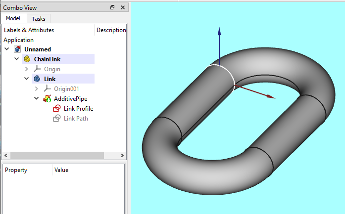
def addLinkPipe(self):
   self.linkPipe =       self.bodyLink.newObject('PartDesign::AdditivePipe','AdditivePipe')
   self.linkPipe.Profile = self.profileSketch
   self.linkPipe.Spine = self.pathSketch
Well all the hard work has been completed and now it’s time to create the additive pipe. How to create an additive pipe in FreeCAD using python is shown in the code above. First we use the “newObject” method of the body object to add a “PartDesign::AdditivePipe”. The we just need to set the Profile and Spine properties to the appropriate sketches that we generated in the code shown earlier.
That’s it! The image above shows the first link in what will become the chain link model that is ready to 3D print.
And Finally…
This post described how to script a sketch in FreeCAD using python. We also described how to script an additive pipe. A detailed explanation of sketch and constraint scripting can be found here. I hope you will look at the other posts in this series on how to model chain links for 3D printing.