This post will describe how to model Chain Link in FreeCAD. All of the modeling is accomplished using a Python script. The Python script allows you to enter the parameters that describe the chain link and then outputs all the objects needed. The chain link model is optimized for 3D printing which means that none of the links touch each other.
This post is for people who just want to run the python macro and generate 3D printable chain links. All of the code is provided below. If you want an explanation of how the code works, then check out these two posts:
- How To Script A Sketch In FreeCAD
- How The Chain Link Python Macro Works With A Custom UI In FreeCAD
If you want to get started creating custom UI’s in FreeCAD then check out this three part series.
If you’re really new to FreeCAD you can start here. You need to have FreeCAD installed in order to run this script.
Install The Chain Link Generator
You need to create two files on your system in order to run Chain Link Generator. The code is provided below you just need to cut and paste.
Chain Link Generator UI File
ChainLinkWidget
0
0
300
383
300
383
ChainLinkWidget
-
12
true
Chain Link Generator
-
Size
-
Length:
-
0.010000000000000
1.000000000000000
-
Width:
-
0.010000000000000
1.000000000000000
-
Diameter:
-
0.010000000000000
1.000000000000000
-
# Links:
-
1
999
-
Units
-
Inches
true
-
mm
-
Scale
-
Scale Factor:
-
0.00009
1.0
-
QFrame::StyledPanel
QFrame::Raised
-
New ChainLink
The code above is the .UI file created by QtDesigner. I have a 3 part series on how to get started with QT if you’re interested but if you just want to run this macro keep reading. The .UI file is an XML file generated by QtDesigner and describes the user interface and all it’s widgets etc.
Simply open up your favorite text editor (I use Notepad on Windows) and copy the text above into the editor. Now save the file on your local hard drive (doesn’t matter where but remember the location as you’ll need it). Name the file anything but the file type should be “.UI”.
Chain Link Generator Python Macro
import FreeCAD,FreeCADGui,Part,Draft
from PySide import QtGui
# Copyright John Singer 2023 CC by 4.0 https://creativecommons.org/licenses/by/4.0/
# CHANGE THE LINE BELOW TO THE LOCATION OF THE UI FILE ON YOUR SYSTEM
path_to_ui = r"C:\Users\jsing\OneDrive - SingerLinks\PERSONAL\FreeCAD\QTPROJECTS\ChainLink\form.ui"

class BoxTaskPanel:
	def __init__(self):
		# this will create a Qt widget from our ui file
		self.form = FreeCADGui.PySideUic.loadUi(path_to_ui)
		self.partChainLink = None
		self.bodyLink = None
		self.profileSketch = None
		self.pathSketch = None
		self.linkPipe = None
		# set default values
		self.linkLen = 2
		self.linkWidth = 1
		self.linkDiameter = .5
		self.scaleFactor = "1.0"
		self.unit = "Inches"
		self.numLinks = 1
		self.initForm()

	def initForm(self):
		print("init form")
		self.form.pb_New.clicked.connect(self.btnNew)
		# initialize values in form
		self.form.dsb_Length.setValue(self.linkLen)
		self.form.dsb_Width.setValue(self.linkWidth)
		self.form.dsp_Diameter.setValue(self.linkDiameter)
		self.form.pb_Inches.checked = True
		self.form.pb_mm.checked = False
		self.form.txt_ScaleFactor.value = self.scaleFactor
		self.form.sb_NumLinks.setValue(self.numLinks)

	def reject(self):
		print("reject - dialog ending.")
		FreeCADGui.Control.closeDialog()
		#self.form.close()

	def accept(self):
		print("accept - dialog ending.")
		FreeCADGui.Control.closeDialog()
		#self.form.close()

	def btnNew(self):
		# user pressed New Chain Link button
		print("Generate new chain link part.")
		if not App.ActiveDocument is None:
			self.runCode()
			self.accept()
		else:
			print("no active document")


	def runCode(self):
		# generate the chain link based on the parameters entered in the form
		print("run code")
		try:
			if self.editForm() == True:
				# create the first link
				self.createPart("ChainLink")
				self.createBody("Link")
				self.createPathSketch("Link Path")
				self.drawPathSketch()
				self.createProfileSketch("Link Profile")
				self.drawProfileSketch()
				self.addLinkPipe()
				self.generateLinks()
		except Exception as e:
			print(str(e))
			QtGui.QMessageBox.information(self.form, 'Error Generating Chain Link',str(e))
		finally:
			App.ActiveDocument.recompute()
			Gui.SendMsgToActiveView("ViewFit")

	def editForm(self):
		# edit the values on the form
		self.linkLen = self.form.dsb_Length.value()
		self.linkWidth = self.form.dsb_Width.value()
		self.linkDiameter = self.form.dsp_Diameter.value()
		if self.form.pb_Inches.isChecked():
			self.unit = "in"
		else:
			self.unit = "mm"
		self.scaleFactor = self.form.txt_ScaleFactor.text()
		self.numLinks = self.form.sb_NumLinks.value()
		# display the values that will be used to generate the Chain Link
		print("Units: {}".format(self.unit))
		print("Len:{} ".format(App.Units.Quantity("{} {}".format(str(self.scale(self.linkLen)), self.unit))))
		print("Width:{} ".format(App.Units.Quantity("{} {}".format(str(self.scale(self.linkWidth)), self.unit))))
		print("Diameter:{} ".format(App.Units.Quantity("{} {}".format(str(self.scale(self.linkDiameter)), self.unit))))
		print("Scale Factor:{} ".format(self.scaleFactor))
		print("Num Links: {} ".format(self.numLinks))
		return True

	def createPart(self, name):
		# create the chainlink part
		print("create the chainlink part")
		Gui.activateWorkbench("PartDesignWorkbench")
		self.partChainLink = App.activeDocument().addObject('App::Part',name)
		self.partChainLink.Label = name
		self.partChainLink.Type = "ChainLink"
		Gui.activateView('Gui::View3DInventor', True)
		Gui.activeView().setActiveObject('part', self.partChainLink)

	def createBody(self, name):
		# create the body for the first link
		print("create the body for the first link")
		self.bodyLink = App.activeDocument().addObject('PartDesign::Body','Body')
		self.bodyLink.Label = 'Link'
		# add the body to the chainlink part
		App.activeDocument().getObject(self.bodyLink.Name).adjustRelativeLinks(self.partChainLink)
		App.activeDocument().getObject(self.partChainLink.Name).addObject(self.bodyLink)
		# make the body the active object
		Gui.ActiveDocument.ActiveView.setActiveObject('pdbody',self.bodyLink)

	def createPathSketch(self,name):
		# create a sketch for the link path
		print("create path sketch")
		self.pathSketch = self.bodyLink.newObject('Sketcher::SketchObject','Sketch')
		self.pathSketch.Label = name
		self.pathSketch.Support = self.bodyLink.Origin.OriginFeatures[3]
		self.pathSketch.MapMode = 'FlatFace'
		self.pathSketch.Visibility = False

	def drawPathSketch(self):
		# draw the sketch for the link path
		print("draw path sketch")
		linkEdgeLen = self.scale(self.linkLen) - self.scale(self.linkWidth)
		# top arc
		self.pathSketch.addGeometry(Part.ArcOfCircle(Part.Circle(App.Vector(25,0,0),App.Vector(0,0,1),50),0,3.14159265),False)
		self.pathSketch.addConstraint(Sketcher.Constraint('Diameter',0,App.Units.Quantity("{} {}".format(str(self.scale(self.linkWidth)), self.unit))))
		self.pathSketch.addConstraint(Sketcher.Constraint('Coincident',0,2,-1,1))
		self.pathSketch.addConstraint(Sketcher.Constraint('DistanceY',0,3,0))
		self.pathSketch.addConstraint(Sketcher.Constraint('DistanceY',0,1,0))
		# left line
		self.pathSketch.addGeometry(Part.LineSegment(App.Vector(0,0,0),App.Vector(0,linkEdgeLen * -1,0)),False)
		self.pathSketch.addConstraint(Sketcher.Constraint('Coincident',1,1,0,2))
		self.pathSketch.addConstraint(Sketcher.Constraint('Vertical',1))
		self.pathSketch.addConstraint(Sketcher.Constraint("DistanceY", 1,2,1,1, App.Units.Quantity("{} {}".format(str(linkEdgeLen), self.unit))))
		# right line
		self.pathSketch.addGeometry(Part.LineSegment(App.Vector(0,0,0),App.Vector(0,linkEdgeLen * -1,0)),False)
		self.pathSketch.addConstraint(Sketcher.Constraint('Coincident',2,1,0,1))
		self.pathSketch.addConstraint(Sketcher.Constraint('Vertical',2))
		self.pathSketch.addConstraint(Sketcher.Constraint("DistanceY", 2,2,2,1, App.Units.Quantity("{} {}".format(str(linkEdgeLen),self.unit))))
		#bottom arc
		self.pathSketch.addGeometry(Part.ArcOfCircle(Part.Circle(App.Vector(self.scale(self.linkWidth)/2,linkEdgeLen*-1,0),App.Vector(0,0,1),self.scale(self.linkWidth)/2),-3.14159265, 0),False)
		self.pathSketch.addConstraint(Sketcher.Constraint('Coincident',1,2,3,1))
		self.pathSketch.addConstraint(Sketcher.Constraint('Coincident',2,2,3,2))
		self.pathSketch.addConstraint(Sketcher.Constraint('Horizontal',1,2,3,3))


	def createProfileSketch(self,name):
		# create an empty sketch for the link profile
		print("create a sketch for the link profile")

		self.profileSketch = self.bodyLink.newObject('Sketcher::SketchObject','Sketch')
		self.profileSketch.Label = name
		self.profileSketch.Support = self.bodyLink.Origin.OriginFeatures[4]
		self.profileSketch.MapMode = 'FlatFace'

	def drawProfileSketch(self):
		# draw the sketch for the link profile
		print("draw profile sketch")
		self.profileSketch.addGeometry(Part.Circle(App.Vector(0.000000,-0.000000,0),App.Vector(0,0,1),10),False)
		self.profileSketch.addConstraint(Sketcher.Constraint('Diameter',0,App.Units.Quantity("{} {}".format(str(self.scale(self.linkDiameter)), self.unit))))
		self.profileSketch.addConstraint(Sketcher.Constraint('Coincident',0,3,-1,1))

	def addLinkPipe(self):
		self.linkPipe = self.bodyLink.newObject('PartDesign::AdditivePipe','AdditivePipe')
		self.linkPipe.Profile = self.profileSketch
		self.linkPipe.Spine = self.pathSketch

	def generateLinks(self):
		print("Generate Links")
		# see if there's only 1 link requested
		if self.numLinks <= 1:
			return
		shiftUp = (float( self.linkLen) - float(self.linkDiameter) - float(self.linkDiameter/3))
		shiftOver = self.linkWidth / 2
		shiftOverQ = App.Units.Quantity("{} {}".format(str(self.scale(shiftOver)), self.unit))
		for ctr in range(1,self.numLinks):
			shiftUpQ = App.Units.Quantity("{} {}".format(str(self.scale(shiftUp)),self.unit))
			clone = Draft.make_clone(self.bodyLink)
			print("Name:{} shiftOver:{} shiftUp:{}".format("Clone-Link{}".format(str(ctr)),shiftOver,shiftUp))
			if ctr % 2 == 0:
				clone.Placement = App.Placement(App.Vector(0.000,shiftUpQ,0.000),App.Rotation(App.Vector(0.000,0.000,1.000),0.000))
			else:
				clone.Placement = App.Placement(App.Vector(shiftOverQ,shiftUpQ,shiftOverQ),App.Rotation(App.Vector(0.000,1.000,0.000),90.000))

			shiftUp = shiftUp + (float( self.linkLen) - float(self.linkDiameter) - float(self.linkDiameter/3))   #- fudgeFactor)
			clone.MapMode = 'Translate'
			clone.Label = "Clone-Link{}".format(str(ctr))
			clone.recompute()
			# move it to the part
			clone.adjustRelativeLinks(self.partChainLink)
			self.partChainLink.addObject(clone)

	def	scale(self, amt):
		scaledAmount = amt * float(self.scaleFactor)
		return scaledAmount

panel = BoxTaskPanel()
FreeCADGui.Control.showDialog(panel)
#panel.form.show()
The code above is the python script.
- Start up FreeCAD and open the Macro’s utility. It’s on the main menu “Macro/Macros…” will bring up the macro dialog box.
- Click the “Create” button. The system will prompt you for a name – call it ChainLink. Notice at the bottom of the screen you see the folder where macro’s are stored. You can change this if you like.
- FreeCAD will open an empty script window. Now just cut and past the python code above into the editor.
- You’ve probably already hit Run and experienced an error. That’s because you haven’t done the next step.
- Modify the code to add the location of your .UI file on your system. It’s at the very top of the script. See below…
path_to_ui = r"C:\Users\jsing\OneDrive - SingerLinks\PERSONAL\FreeCAD\QTPROJECTS\ChainLink\form.ui"Change the file name to whatever you named the .UI file you created earlier. The python script will convert the XML in the .UI file to the appropriate Qt python code to display the user interface.
Run The Chain Link Generator
Hopefully, everything is installed correctly and you can hit the run button in FreeCAD to run the macro. When you run the macro a dialog box will appear in the “Task Panel” on the left hand side of the screen. See below:
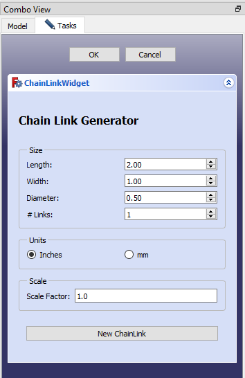
The dialog box above appears in the “Task Panel” in FreeCAD. You specify the chain link to be generated by entering the parameters into the dialog:
- Length – this is the overall length of the link.
- Width – this is the overall width of the link.
- Diameter – this is the diameter of the material that makes each link.
- # LInks – this determines how many links will be in the chain link.
- Units – you can select either inches or millimeters for the unit of measure.
- Scale – The scale factor will scale the model up or down. The default is one which means there will be no scaling. This allows you to specify the chain link in its actual size and then scale it down to any size you want.
Once you’ve entered the parameters as you want them, click on the “New ChainLink” button. This will run the code and generate the chain link model.
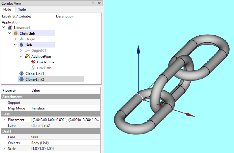
Here is an example of a generated chain link. There where 3 links generated and note how every other link is rotated 90 degrees. Also note that the links are “loose”, i.e. they don’t touch each other. This is done so that you can export the chain to an STL file and it is ready to be 3D printed.
And Finally…
I hope you get some good use out of this macro which shows you how to model Chain Link in FreeCAD. 3D printing chain link demonstrates a powerful ability of 3D printers and will surely impress your friends. Remember if you are interested in an explanation of how the code works check out the posts linked at the beginning of this post.