This post will focus on how to design and 3D print gears using Blender. For this effort I purchased an addon called Precision Gears from Maker Tales. Blender is the 3d modeling CAD software I use for all my 3D printed projects. Modeling gears from scratch is not easy although you can find tutorials on the subject. It’s much easier to use an add-on. The $8 dollar price tag seems like a great deal considering how much functionality comes in this add-on. This post has a number of pro tips you won’t find elsewhere…
Goal
For this post our goal is to create a “spur” gear that can be attached to a stepper motor. This is part of a larger project that will use the spur gear to drive a rack gear. If you are new to gears, you might want to find some basic gear tutorials on the web. This wiki page is good start. The first thing you might notice is the mathematics behind how gears work especially how to get two gears to mesh together correctly. Well don’t worry, Precision Gears does all the hard work for you as long as you follow a few simple rules which will be explained in this post.
Design The Spur Gear
A spur gear is a round gear with the teeth on the outside. For my project the spur gear will be attached to a stepper motor which will provide the power to the machine. First we will use Blender and Precision Gears to design the spur gear. First you have to download the Precision Gears addon and install it in Blender. The free version does spur gears so for this post that’s all you need. If you plan to go beyond simple spur gears you might want to buy the complete package. Once you have the addon installed go through the following steps in Blender:
1 – Setup Blender For Millimeter
It’s important to get Blender setup for designing in millimeters or you will have issues with scaling etc. Since we are planning on printing the gears it isn’t likely you’ll be doing anything measured in meters. Open a new blender and follow these simple steps:
File / New / General – this will create a new blender using your current default settings.
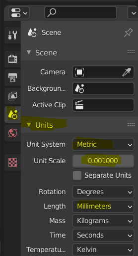
Change the scene unit settings. Click on the Scene icon and look at the Units settings. Change “Unit System” to metric and “Length” to Millimeters. Now change the “Unit Scale” to .001. Now you are working in millimeters. You might notice the grid is now very large. Keep reading…
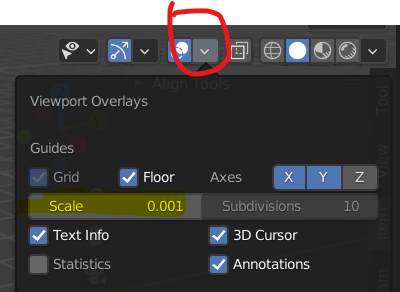
Change the viewport overlay settings. Click on the down arrow as shown above. Change the “Scale” to .001. This will provide a usable grid.
Optionally, you can save these settings as your defaults. You might want to delete the default cube, light source, and camera as you probably don’t need those either.
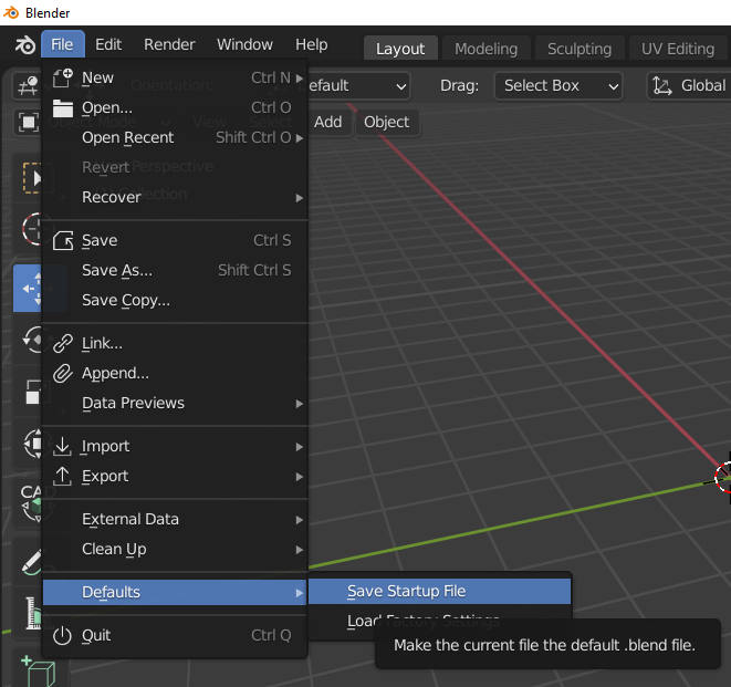
File / Defaults / Save Startup File – this will prompt you to save the current blender file as your default startup file. Once again, this is optional for this post.
2 – Create The Gear
Gear Parameters
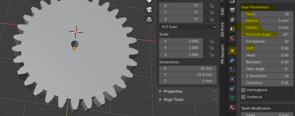
After creating the gear, select it so you can modify it’s properties. Click on the object data properties icon and this will show you the “Gear Parameters”. It’s important to realize that the size of the gear is driven by the parameters so don’t use scaling operations on the gear object. The important parameters are highlighted in the screenshot above.
- Teeth – this defines the number of teeth. The gear will get larger or smaller to hold all the teeth.
- Module – this is the distance between the base of the teeth. This will also impact the size of the gear.
- Height – this is the height of the gear.
- Pressure angle – this is the angle that goes from the middle of the tooth to the end.
- Shift – I set this to zero.
This creates the basic gear size that I’m looking for. Your needs will be different but this is the basics of how to create the gear.
If you want two gears to mesh together – they have to have the same “module” and “pressure angle”.

Let’s look at some more parameters. The section called “Teeth Modification” I don’t use so all the values are zero.
The section called “Bore” controls the hole in the center of the gear. I need a 4mm hole so I entered a “radius” of 2mm. The “Cutter Position” and “Cutter Scale” allow you to make non-circular holes for example adding a flat surface on one side of the hole. Also check out the “Type” dropdown for more complex hole shapes.
Finally, the section called “Extrusion” will add a cylinder above the gear that you might use for the set screw. I’m going to put my set screws right in the gear so the extrusion parameters are zero.
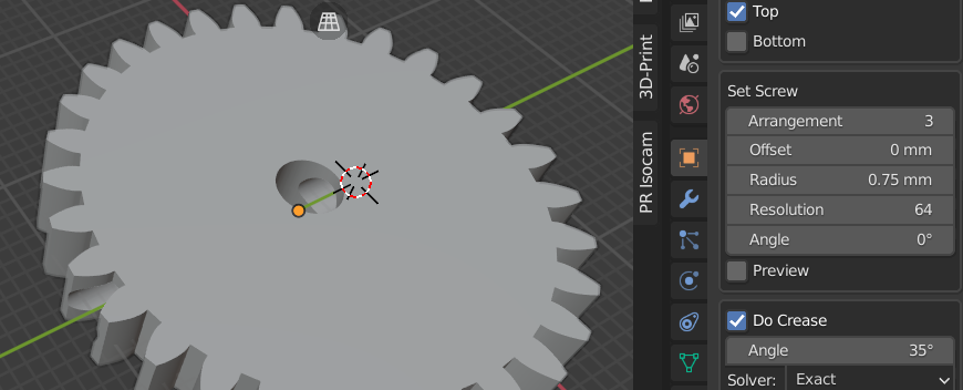
The next section is called “Set Screw”. This will create a hole through the gear to the center “bore” hole. You use a set screw to tighten down on the shaft of the stepper motor.
- Arrangement – this number controls the number of set screw holes and how they are arranged. I entered 3 which creates two set screw holes on opposite sides of the bore hole.
- Offset – this moves the set screw hole up or down on the gear.
- Radius – I’m using 3mm set screws so the radious is .75
Adding a Hole For a Nut
Precision Gears is great but there’s one thing it doesn’t do. I’m using a 3mm set screw but I need something for the set screw to “screw” into. The set screw hole is just that – a hole with no threads. To solve this problem, we will create a hole that we can drop a 3mm nut inside the gear. This will make more sense when we assemble the gear to the stepper motor.
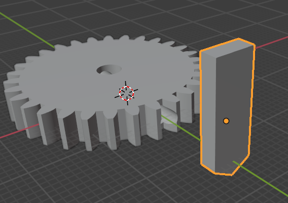
The highlighted object above is the “nut wedge”. It’s a cube with the end pointed to match the size of the nut. The wedge width is the width of the nut.
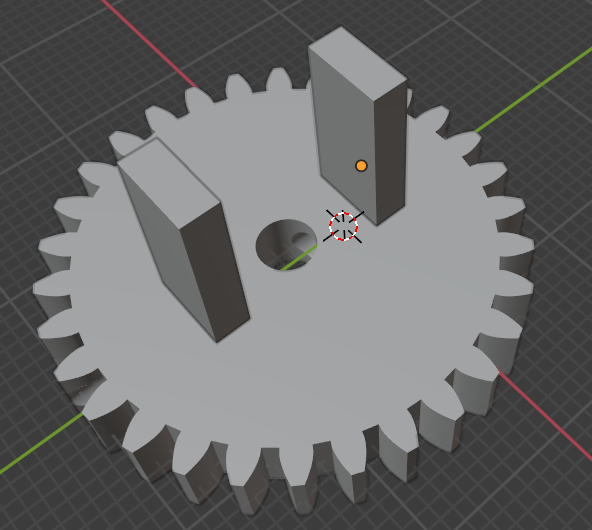
Copy the “nut wedge” and position them where you want to drop the nuts inside the gear.
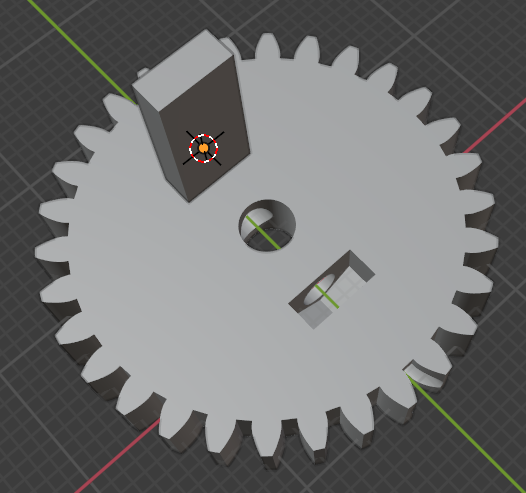
Finally, we add a boolean modifier to the gear and pick the nut wedge as the object to cut into the gear. The screen shot below shows the gear after the boolean operation. You can see the hole in the gear that we will use to add a nut for the set screw.
3D Print The Gear
I printed the gear on both an FDM printer and a resin printer. The resin printer definitely produces a better result with cleaner edges on the gear teeth, the bore hole and set screw holes. The FDM printer produces a perfectly usable gear, but I would recommend setting the fill factor to 100%. The gear pictured below is from the resin printer.
Attach The Gear To The Stepper Motor
Here we look at the installation of the gear on the stepper motor.
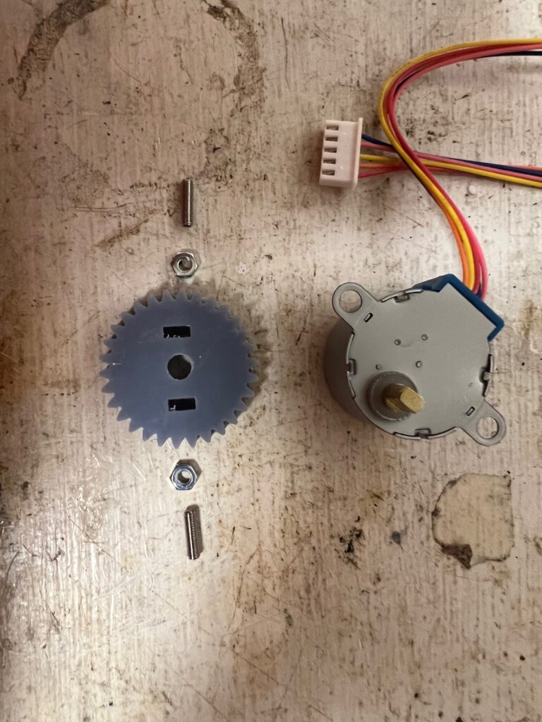
This is the gear with the two nuts and set screws lined up ready to install. If you look at the post on the stepper motor you see it has two flat sides which is why I needed two set screws.
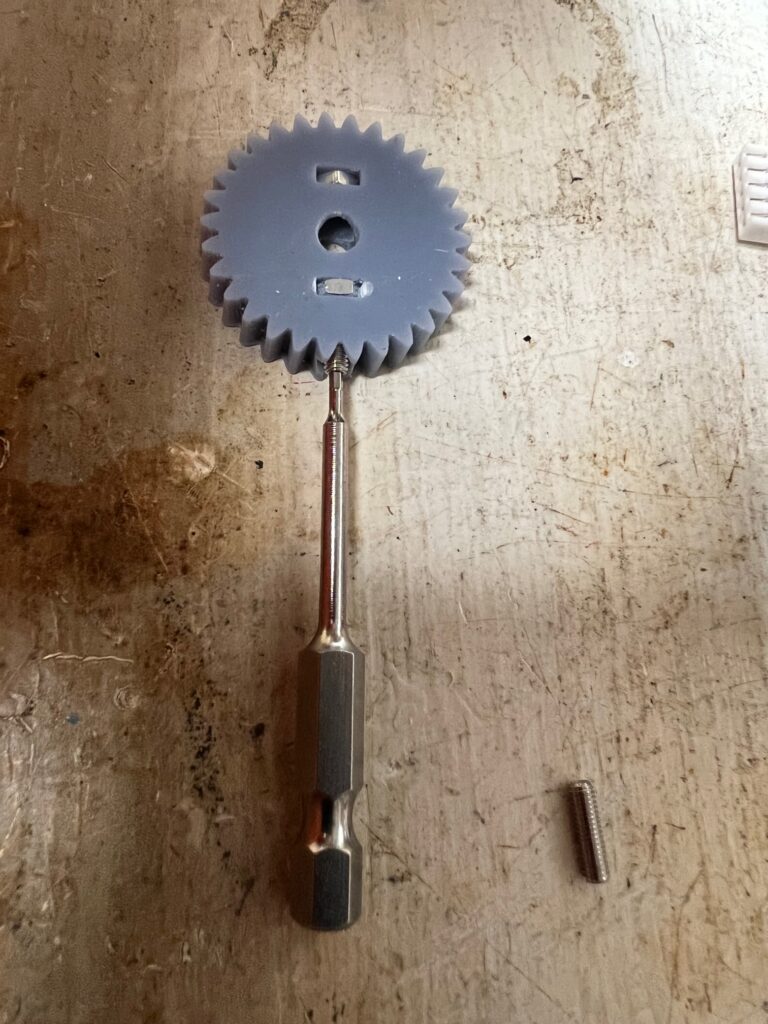
In this picture the two nuts have been pushed into the gear and one of the set screws is being screwed into the nut. The set screw has a 1mm hex head for tightening.
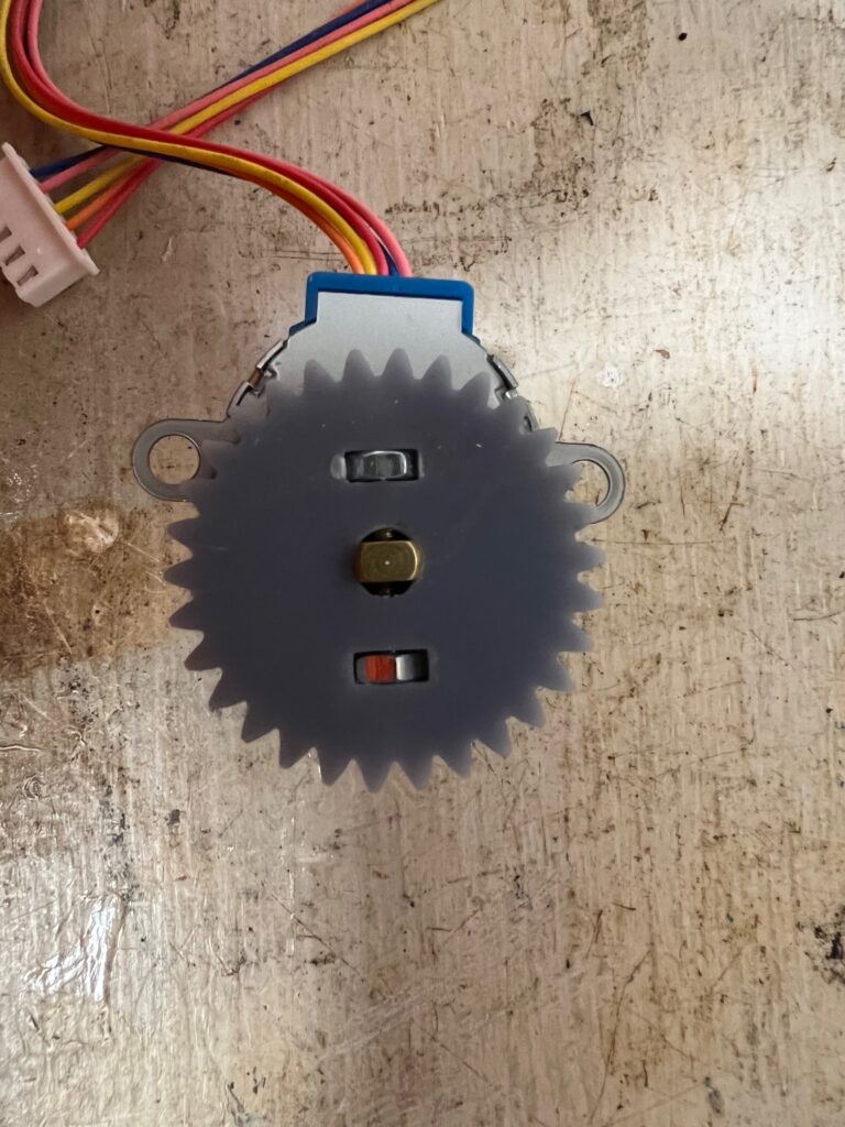
Here is the gear fully installed. Both set screws have been tightened evenly to center the post in the hole. I should note that the Precision Gears addon has a facility for creating non- circular bore holes that match the flat edges of the axle, but I didn’t use it on this example.
And Finally…
In this post we covered how to design and 3D print gears for your mechanized projects. We used Blender and the Precision Gears addon to create the gear. Once you export the STL file from Blender you can use your favorite slicer and 3D printer to print the gear.
For other Maker Space posts on my website go here.